Wiring diagrams and connector pinouts#
Updated October 14, 2026 For installers
The functions of the programmable inputs and outputs are set on the configuration website, Settings tab. Output polarity (+/−) is switched on the website next to each output. The "Typical connection" column follows the wiring diagram; where nothing is specified, connect as needed.
Connector locations#
All connectors are on one end of the unit: the Ext. Antenna connector on the left, and X2 (10 pins) and X1 (18 pins) closer to the center.
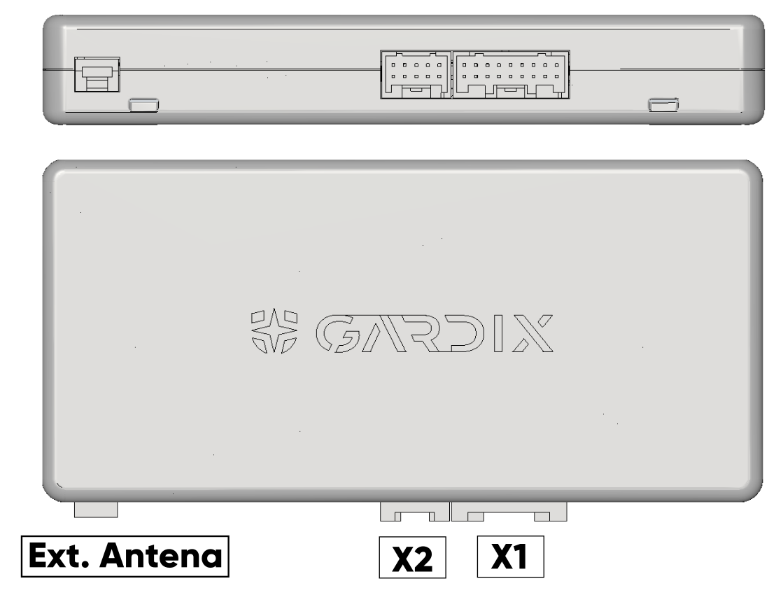
X1 — main (18 pins)#
The connector is shown from the wire side. The pins are in two rows of 9: odd numbers in one row, even numbers in the other. Pin 1 (red, +12 V) and pin 2 (black, ground) are the end pair.
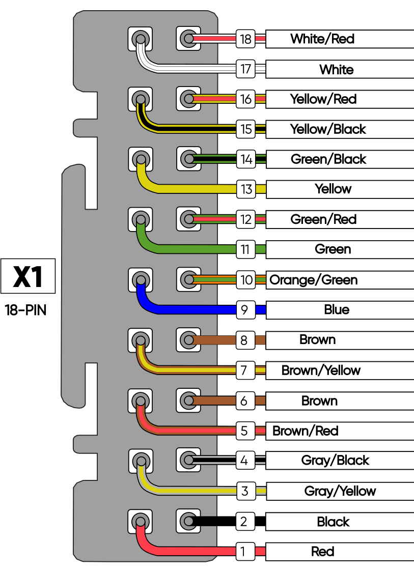
| # | Color | Function | Typical connection |
|---|---|---|---|
| 1 | Red | +12 V power (VCC) | +12 V battery via a 3 A fuse |
| 2 | Black | Ground (GND) | Ground |
| 3 | Gray/yellow | Analog input (+) | Resistive (steering wheel) buttons |
| 4 | Gray/black | Analog input (−) | Resistive (steering wheel) buttons |
| 5 | Brown/red | CAN1 High | Car CAN bus |
| 6 | Brown | CAN1 Low | Car CAN bus |
| 7 | Brown/yellow | CAN2 High | Car CAN bus |
| 8 | Brown | CAN2 Low | Car CAN bus |
| 9 | Blue | Programmable input (+) | — |
| 10 | Orange/green | Programmable input (−) | Panic button (−) |
| 11 | Green | Programmable input (+) | — |
| 12 | Green/red | Programmable input (−) | — |
| 13 | Yellow | Programmable input (+) | — |
| 14 | Green/black | Programmable input (−) | Hood switch (−) |
| 15 | Yellow/black | Programmable output 1500 mA (+/−) | Siren (+) |
| 16 | Yellow/red | Programmable output 330 mA (+/−) | Wired blocking |
| 17 | White | Programmable output 330 mA (+/−) | — |
| 18 | White/red | Programmable output 330 mA (+/−) | — |
X2 — additional (10 pins)#
The connector is shown from the wire side. The pins are in two rows of 5, numbered the same way as X1: odd numbers in one row, even numbers in the other.
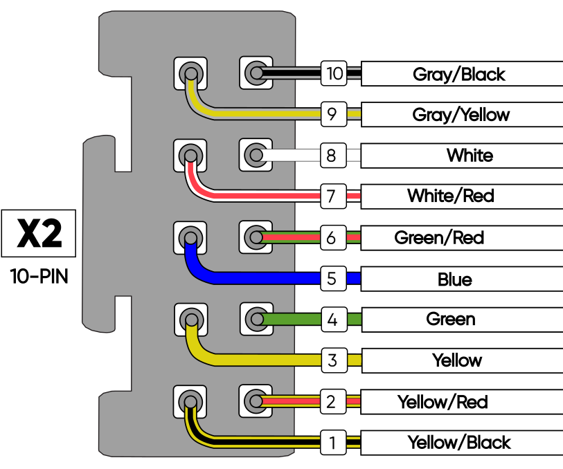
| # | Color | Function | Typical connection |
|---|---|---|---|
| 1 | Yellow/black | Programmable output 1500 mA (+/−) | Hyundai autostart: IGN1, see Autostart |
| 2 | Yellow/red | Programmable output 330 mA (+/−) | Hyundai autostart: IGN2 |
| 3 | Yellow | Programmable output 330 mA (+/−) | Hyundai autostart: ACC |
| 4 | Green | Programmable output 330 mA (+/−) | — |
| 5 | Blue | Programmable output 330 mA (+/−) | — |
| 6 | Green/red | Programmable output 330 mA (+/−) | Autostart starter (+) |
| 7 | White/red | LIN 1 | Depends on the car, see Autostart |
| 8 | White | LIN 2 | Depends on the car, see Autostart |
| 9 | Gray/yellow | LIN 3 | Depends on the car, see Autostart |
| 10 | Gray/black | LIN 4 | Depends on the car, see Autostart |
LIN 1 – LIN 4#
Pins 7–10 are multi-purpose LIN buses. Their function depends on the car make and model: for example, on Toyota, Lexus and Hyundai, autostart is connected through them. See Autostart.
Ext. Antenna (3 pins)#
The connector for the Gardix GeoAntenna External GPS antenna.
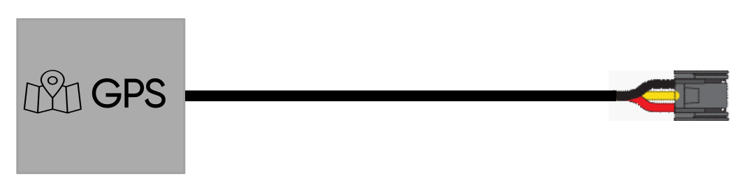
| # | Color | Function |
|---|---|---|
| 1 | Red | +12 V |
| 2 | Yellow | One-wire data bus |
| 3 | Black | Ground |
AirRelay relay#
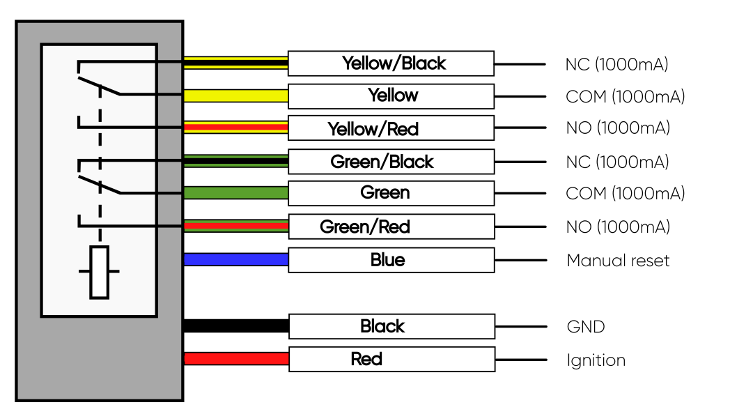
| Color | Function |
|---|---|
| Yellow/black | NC contact (1000 mA) |
| Yellow | Common contact (1000 mA) |
| Yellow/red | NO contact (1000 mA) |
| Green/black | NC contact (1000 mA) |
| Green | Common contact (1000 mA) |
| Green/red | NO contact (1000 mA) |
| Blue | Manual reset |
| Black | Ground (GND) |
| Red | Ignition |
Relay power
Connect the AirRelay relay to the ignition signal, not to constant +12 V.
After installation, add the relay to the security system.